 Placing equipment racks
|
Tool |
Tool set |
|
Equipment Rack 2D
Equipment Rack 3D
|
Layout |
Both 2D and 3D equipment racks can be created. The 2D version represents a front view of a rack. The 3D version displays an associated existing 2D rack in 3D views. The 2D version and 3D version are placed on different layers that automatically display the rack in an appropriate view. A 3D equipment rack can connect to a cable network, and is considered to be a drop point; the connection occurs at the center rear of the rack. To connect rack-mounted equipment to a cable path network, connect the rack.
Optionally, a 3D rack could represent a stand-alone, generic 3D view of a rack or console for a concept drawing.
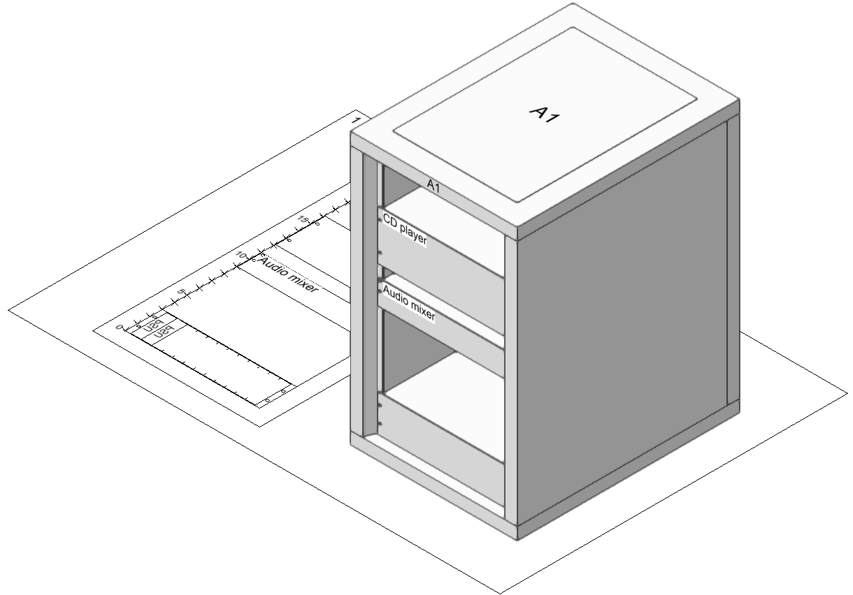
Equipment and rack frames placed within a rack are associated with that rack for display, identification, and reporting purposes, and move with the rack.
To place an equipment rack:
Ensure that the current design layer is Rack Elevation when placing 2D racks, and Rack 3D Layout when placing 3D racks. This coordinates with the view settings for the design layers and the viewports on the sheet layers, for proper display.
Click either the Equipment Rack 2D or Equipment Rack 3D tool.
Click to place the equipment rack. The first time you use the tool in a file, a properties dialog box opens. Set the default parameters. The parameters can be edited later from the Object Info palette.
To associate a 2D equipment rack with a 3D rack, select the existing 2D rack from the Rack ID list. The 3D rack displays a model of the 2D rack. The association remains unless the 2D rack is deleted.
Click to show/hide the parameters.Click to show/hide the parameters.
|
Parameter |
Description |
|
General |
|
|
Rack ID |
Enter an identifier for the 2D rack; equipment and rack frames placed in the rack inherit this ID as a read-only parameter that identifies their location. For a 3D rack, select the existing 2D rack to display in 3D, or select <None> to create a generic 3D rack or console that is not associated with a 3D rack. |
|
Rack Style (3D only) |
Select rack or console style for the 3D rack |
|
Physical (2D only) |
|
|
Height RU |
Select a standard height for the rack |
|
Width/Depth |
Enter the dimensions of the rack in document units |
|
Power Consumption |
Specify the total power requirement of the rack and the equipment it contains |
|
Weight of Rack |
Enter the weight of the rack only |
|
Total Weight |
Specify the total weight of the rack plus the equipment it contains |
|
Configuration |
|
|
Rack Opening (2D only) |
Select a standard rack opening width (equipment cannot be wider than this value, to be able to fit into the rack opening) |
|
Console Slope (3D only) |
For a console type of rack, enter the slope value in degrees |
|
Panel Thickness (3D only) |
For a console type of rack, enter the thickness to model the cladding surrounding the panel |
|
Location (2D only) |
|
|
Room ID |
Displays the room ID, if the equipment rack is contained within a layout room |
|
Display (3D only) |
Select the portions of the rack to draw in 3D; drawing more parts will look more realistic, but take longer. Show Power and Show Weight can only display values for an associated 2D rack. |
Viewing front and rear mounted equipment
Some equipment is mounted to the front, and some to the rear, of the equipment rack, based on the Mounting selection in the Object Info palette of a selected device. For times when you need to see only equipment mounted in the front or rear configuration, use the CC-Equipment-Front and CC-Equipment-Rear classes to control the visibility of the equipment.
In a viewport, accopmplish the same effect by using viewport class overrides to control the visibility of the CC-Equipment-Front and CC-Equipment-Rear classes in the viewport.
